Multitasking the Arduino Part 2 Circuit Diagram Timer 0 is one of the main timers/counters in the 8051 microcontroller, used for doing timing operations and counting events. It is divided into two 8-bit registers they are TL0 (Timer 0 Low byte) and TH0 (Timer 0 High byte). By combining both, these form a 16-bit timer/counter. TL0 (Timer 0 Low Byte) TL0 is the lower 8-bit register of Timer 0.
Electronics projects based on ATmega32 microcontroller of AVR series. These ATmega32 projects and tutorials are explained with the help of schematics, source codes and videos. In this project we are going to design a simple Alarm clock using ATMEGA32 timers. ATmega32A microcontroller has a 16 bit timer… July 15, 2015. 4x4 Keypad The Arduino-Timer library is a community-contributed library that enables users to configure timer-based events (tasks) without the need to do register-level programming for the timer modules. It uses the built-in timer-based millis and micros functions, so it's like a wrapper layer of useful APIs on top of the built-in timer-based functions.

8051 Timers and Counters Circuit Diagram
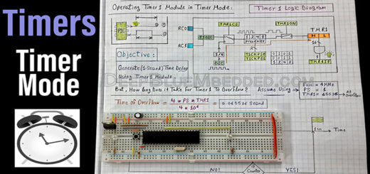
Tout - The Cycle Time after the division. 4 - The division of the original clock (4 MHz) by 4, when using internal crystal as clock (and not external oscillator). Count - A numeric value to be placed to obtain the desired output frequency - Fout. (256 - TMR0) - The number of times in the timer will count based on the register TMR0. This microcontroller is used in Arduino which is a popular ready made easy to use microcontroller based system. The microcontroller contain Timers and Counters which are useful for creating time based interrupt, create counting mechanism for counting external events, creating signal waveform, for generating PWM signal for motor controls etc.

Real-Time Clock (RTC) These are low-resolution timers as compared to General purpose and Systick Timers. They are used to provide time in a human-readable form to the end-user and hence their resolution is usually 1 second. Its basic use is to tell the present time to the end-user, in other words, it acts as a digital watch.
PIC16F877 Timer Modules tutorials Circuit Diagram
The time it stays HIGH is decided by the size of a resistor and a capacitor. The higher the values, the longer it stays HIGH. If you connect a buzzer to the output, you can create an alarm circuit that is triggered for example by a window being opened. 555 Timer One-Shot Example Circuit. The following circuit turns on an LED when you push the
